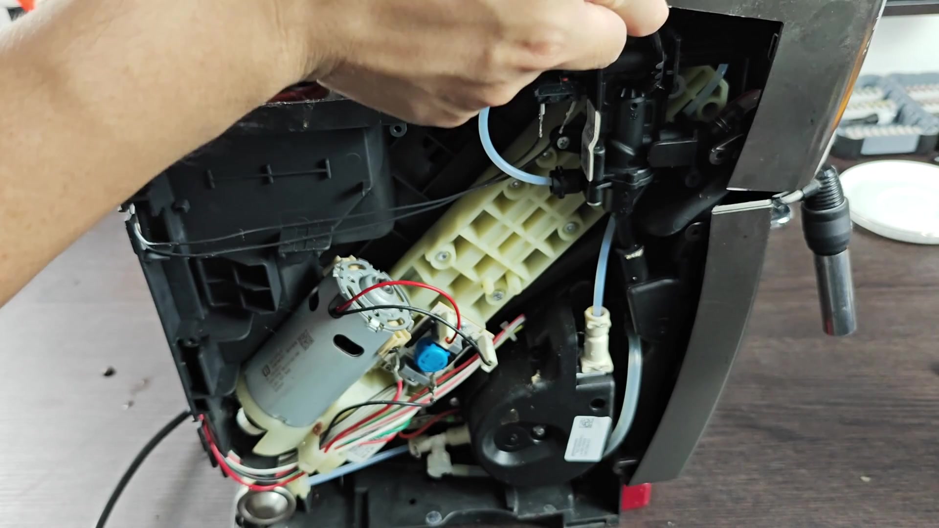
Safety first, so turn off your De’Longhi Magnifica S Smart before removing it to start taking it apart. Remove it from the wall socket right away to avoid potential electrical shock. The most important thing you can do is unplug it before even starting on the screws or inside parts of machine.
Next, lift water tank straight up and out of its housing. After that, the grounds collector snap out easy with little effort. Once you remove those two part, you will have enough space to keep taking apart the front.
Internal Components Inspection
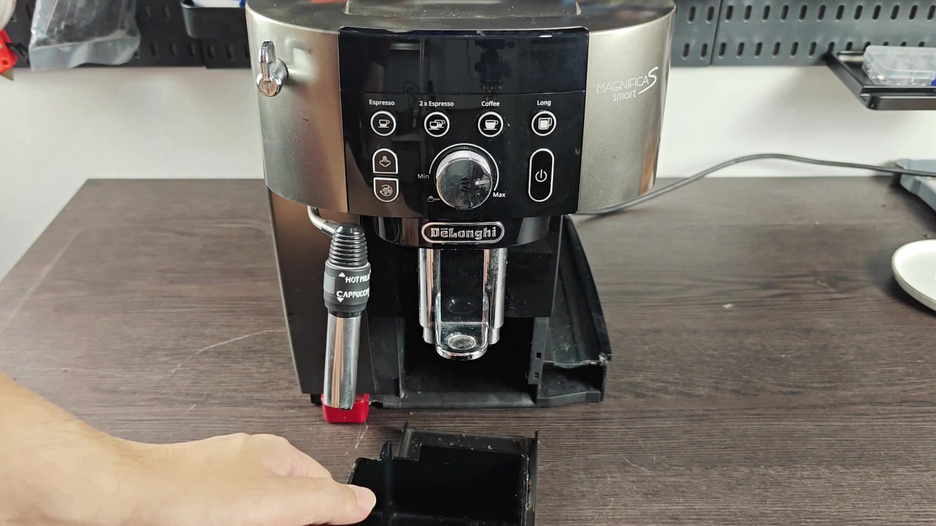
Sliding the main drip tray forward and pulling it completely out allow for access to the rear section. The black grounds container is behind what would be the position of the drip tray and you’ll see a handle on it. Lift it away.
You can see now more of the structure that makes up the front panel with the long coffee and espresso buttons still in view. Then look for the access panel on the outside casing, facing side of the machine. It’s secured with screws or clips under there, so pull off that side cover and take a quick peek inside. Even though it may be a jumble of parts inside, you’ll immediately notice the barcode sticker to verify that you’re headed in the right direction.
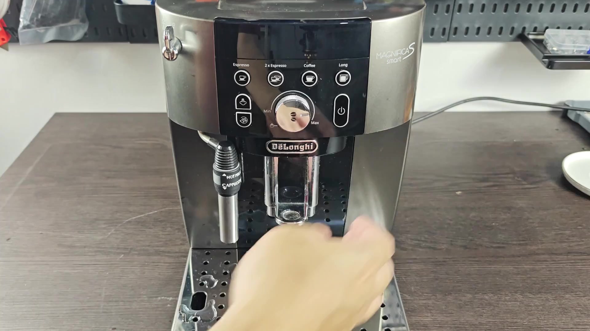
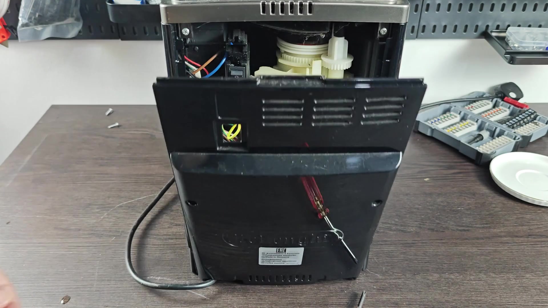
Move around to the back of the machine where actual tools is required. Remove the rear panel by unscrewing fasteners that hold it on. Be careful not to strip the screws when removing them.
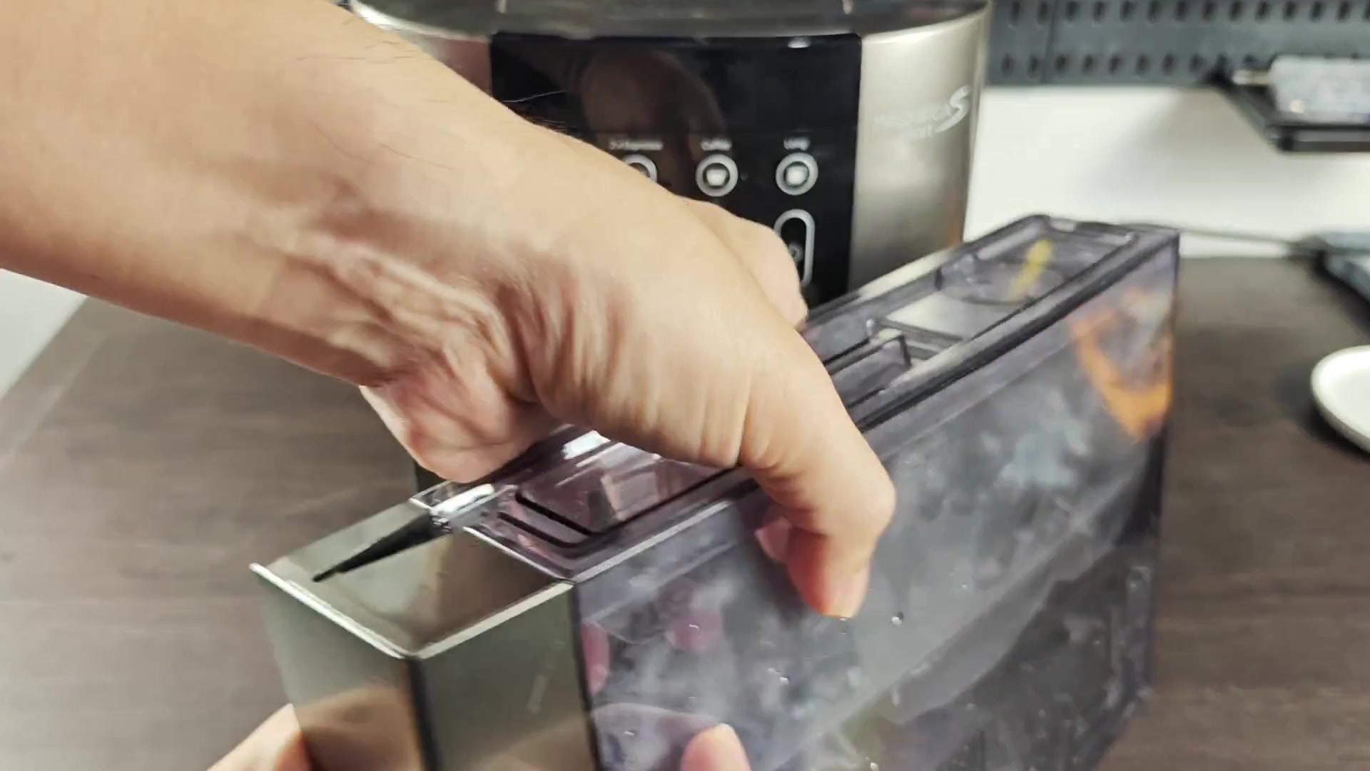
Once all screw have been removed, lift the back cover off which leaves the white plastic assembly visible along with all its wiring. The DeLonghi raised text remain intact on the now detached cover.
But then zoom in on that section of circuit board. See those wires that connect from one end to another? There are bar codes, labels, and red and white connector thingamajigs around to the left of all this. It’s confusing. It doesn’t make much sense at first glance; some words is there but you can’t read them and it’s all just a bunch of stuff connected to other stuff in ways that might seem complex; and it is.
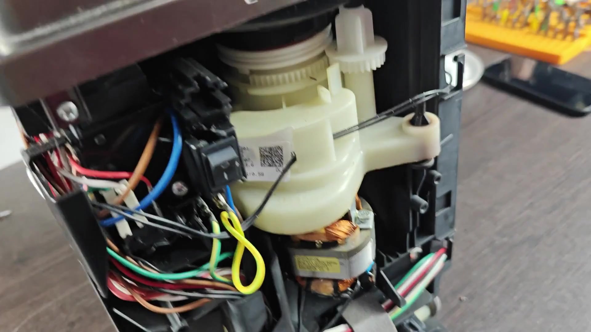
Looking at the power switch assembly you’ll notice a black rocker switch that has I and O symbols next to it. To the side, you can see some bundles of multi-colored wires running near them. There is also a white plastic gear drive unit near here too. You can see a small label with a QR code, but it might be hard to read; however, it helps show how things are laid out.
Move down the chassis now for some translucent hoses that span the frame. They is held together by a small white connector block with many pins. One of them is labeled ULKA on top of a green cap.
You will notice wiring harnesses crossed everywhere else too. At first glance, this look like a tangled mess, but later you’ll be able to follow it.
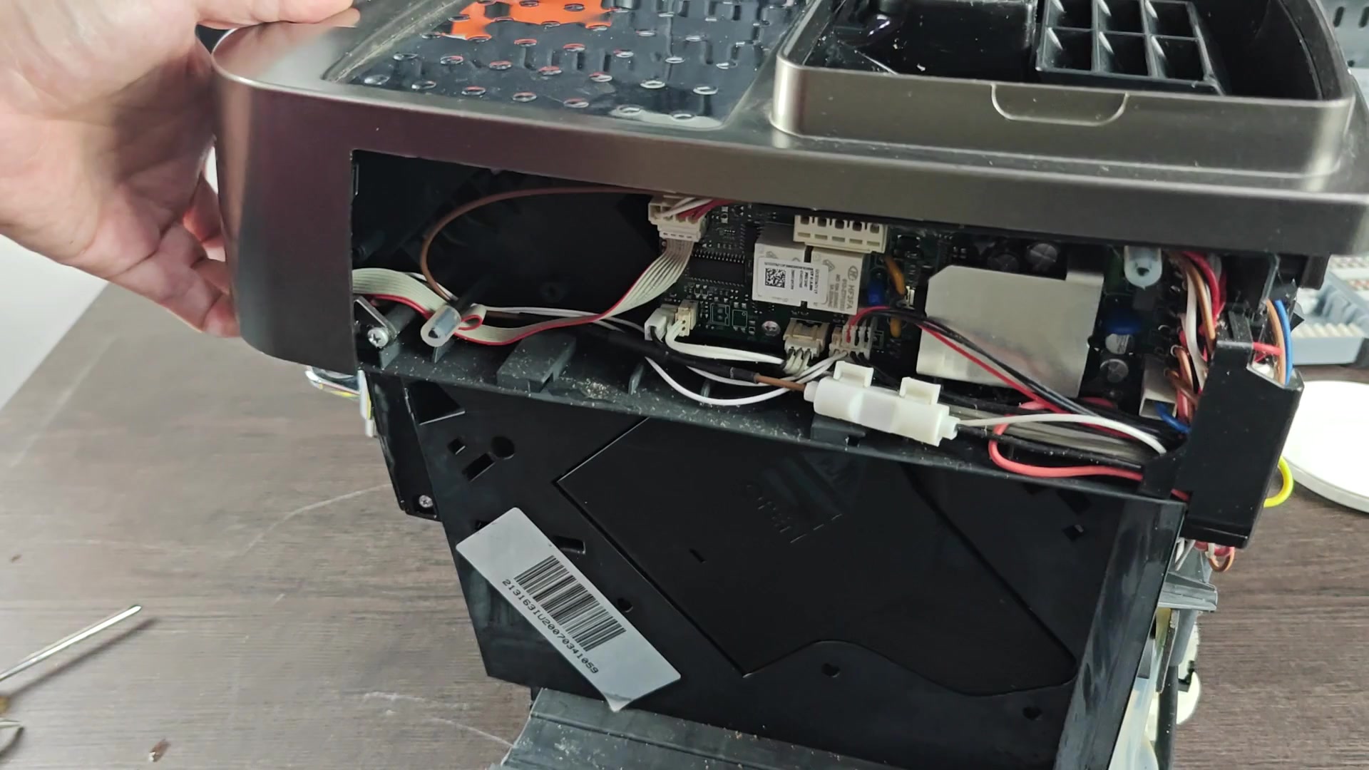
Now zoom in closer at the main printed circuit board. It’s green and we’ve got a bunch of white connectors connected to it. You can see one end of a ribbon cable running down it, and another small module have its own QR-code label.
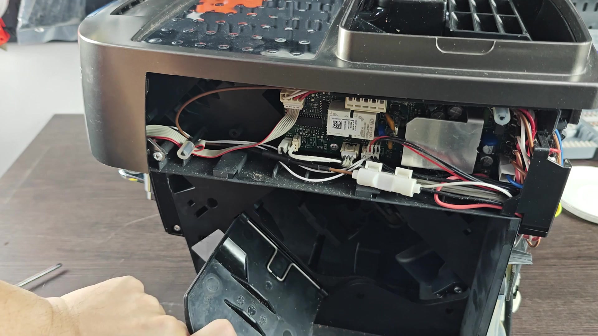
Some red and black wires connects somewhere else. The components are packed pretty tight here, no room for errors when you put it back together.
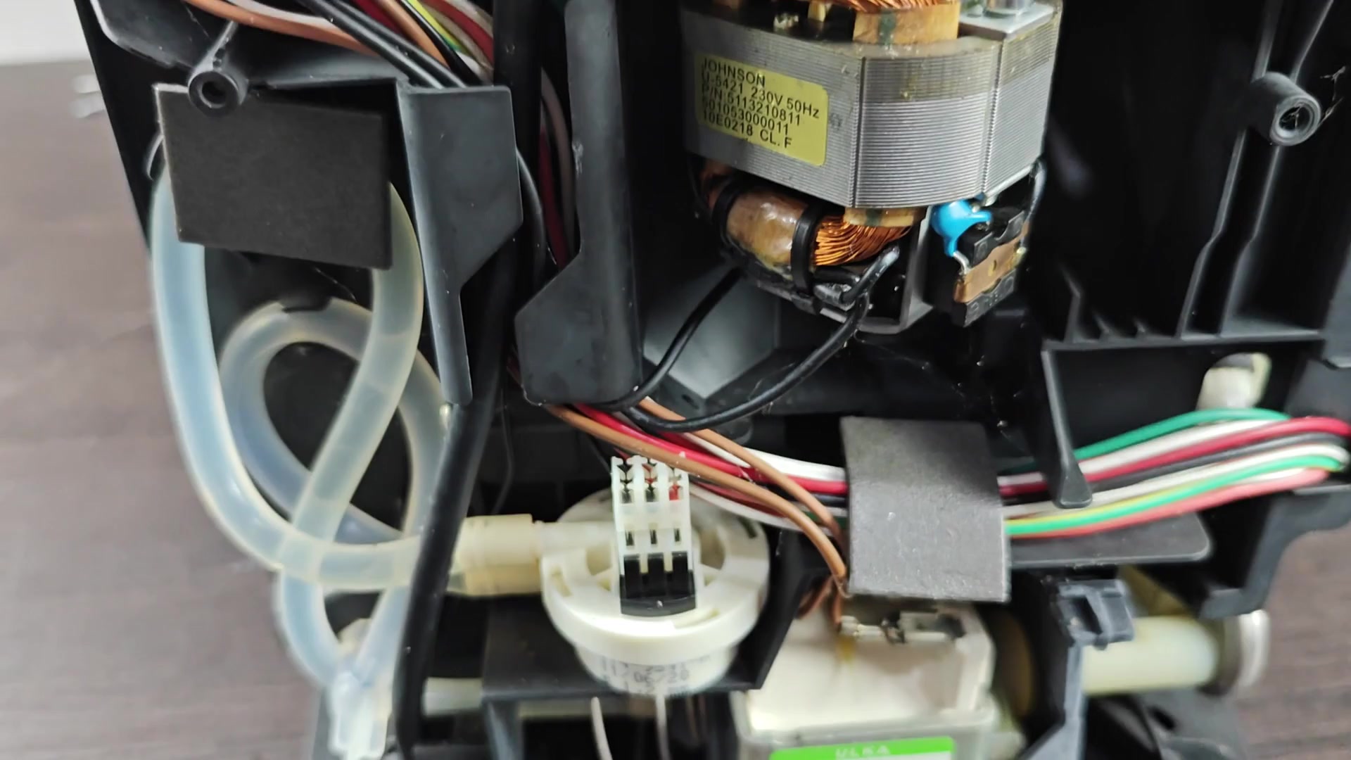
Jump back over to the mechanical side of things; you’ll see a big white plastic drive unit for the gears there. Wires is all over this thing. That is why you will find another motor nearby (this one has copper windings). If you need to reach in and make an adjustment near the front, just know you’re going deep into the cavity and it can feel cramped while working in there.
Use some added torque from a SKIL power drill to loosen things up. Position the drill against a fastener on the unit and you’ll have those screws removed in no time, quick and clean. It’s a perfect job for the drill, which makes it go way quicker than ever before. We should of had enough done to get through in one sitting.
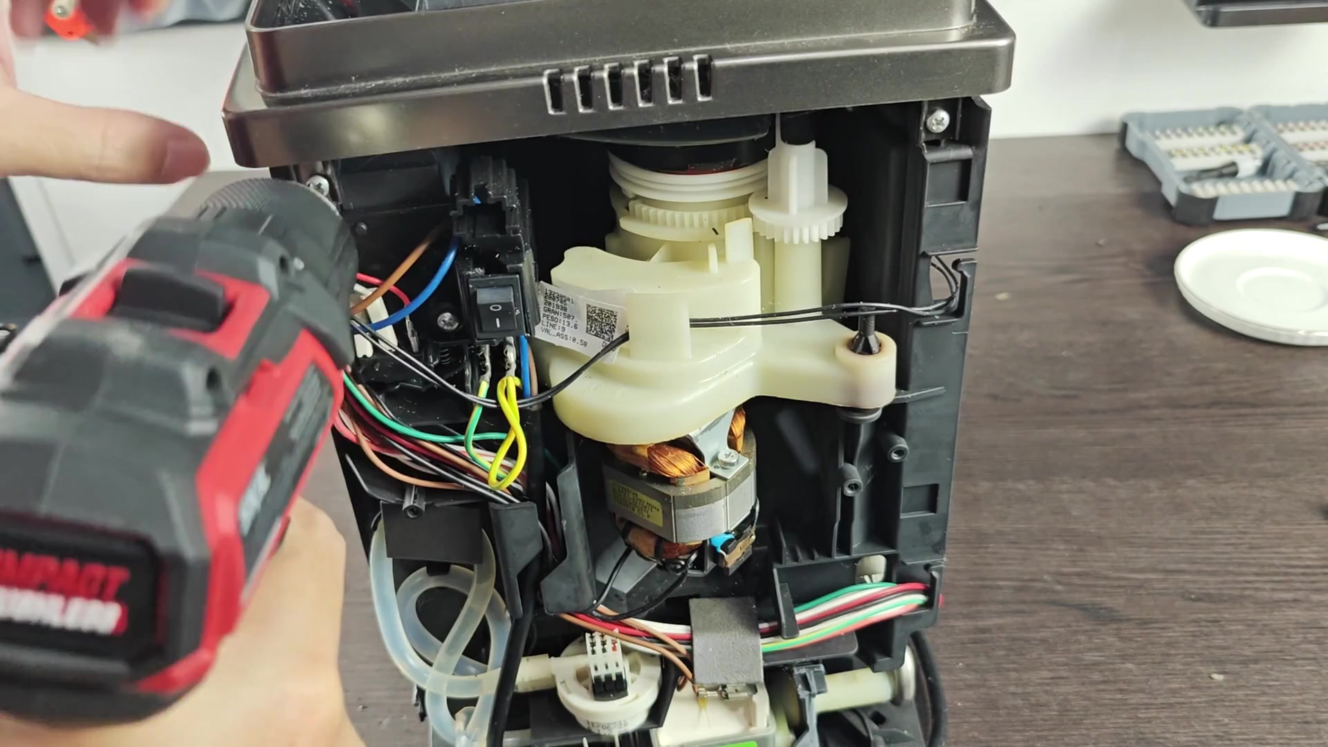
Okay, time for a quick rewind. Coffee beans has been resting in the top hopper area. On the right side is an arm that extends inward toward the front to hold a black tube connector.
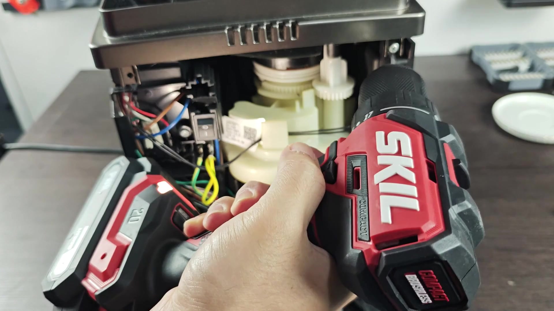
There aren’t any labels you can read to get your bearings here, but don’t worry: matching what you see visually and using your instincts will be enough (it always seems to work out).