A can opener, such as this one from Hamilton Beach, can be dismantled and the mechanism checked inside. A gear could become stuck or a component could dry out, making the appliance useless. Because these are so cheap, it’s worth considering tossing the unit entirely.
But even if you do that, take a look inside for curiosity (or education). The outer shell looks straightforward and doesn’t make you think there is much complexity in there. To get started, you turn it upside down and get at the bottom of the unit. The back cover is held on by several screws that are removed fairly simply. After the final screw is released, it come apart in two pieces easily. Everything mostly just clicks together with very little effort.
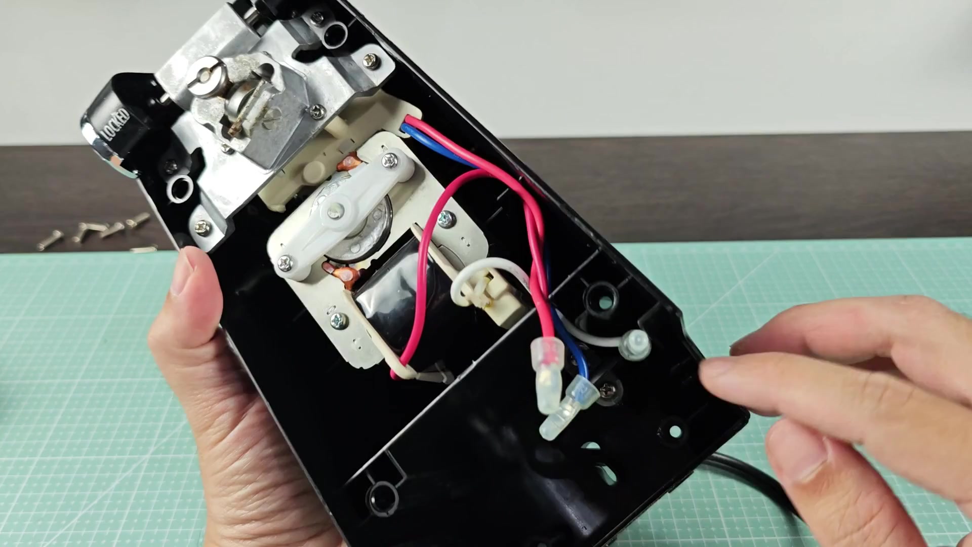
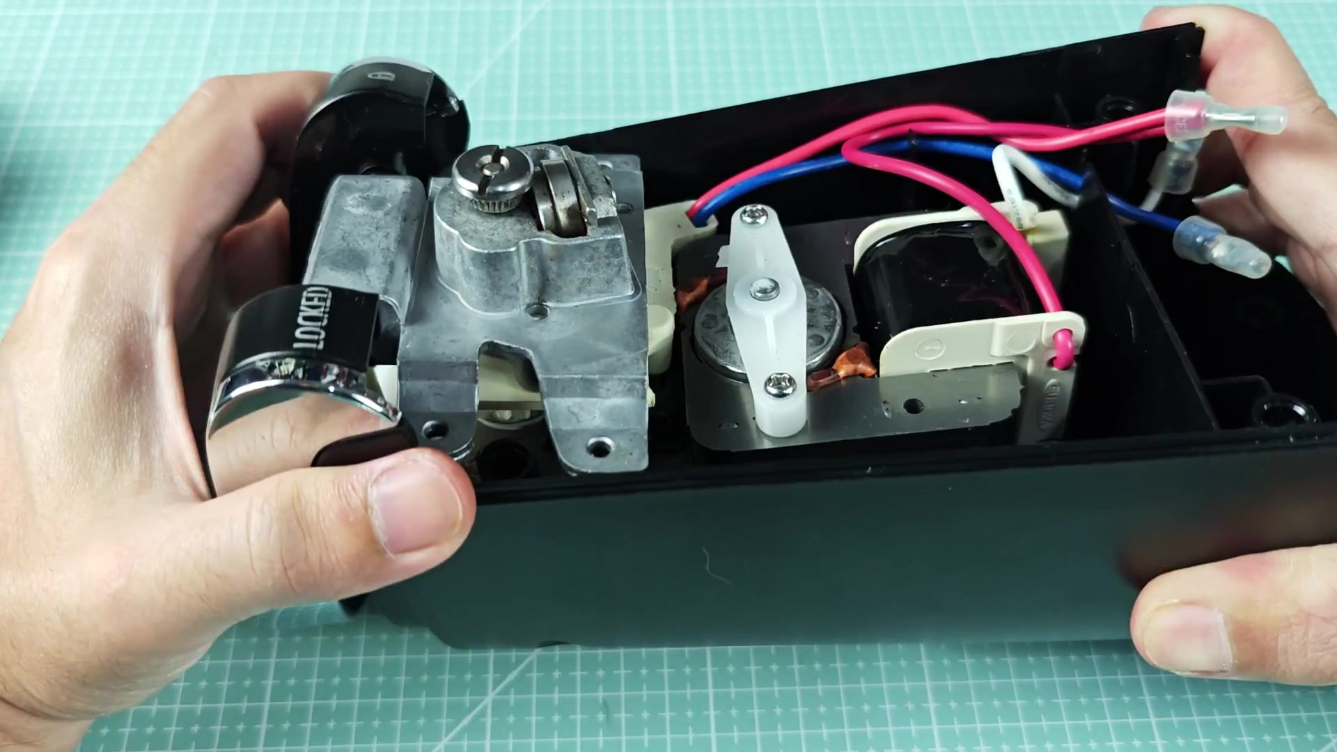
Inside, there isn’t much room for this size of a unit but everything is compact. A gear assembly sits next to the motor and they’re connected via some red and blue wires. It looks like it could be fragil but seems solid enough for everyday wear and tear.
Internal Gear Mechanism Analysis
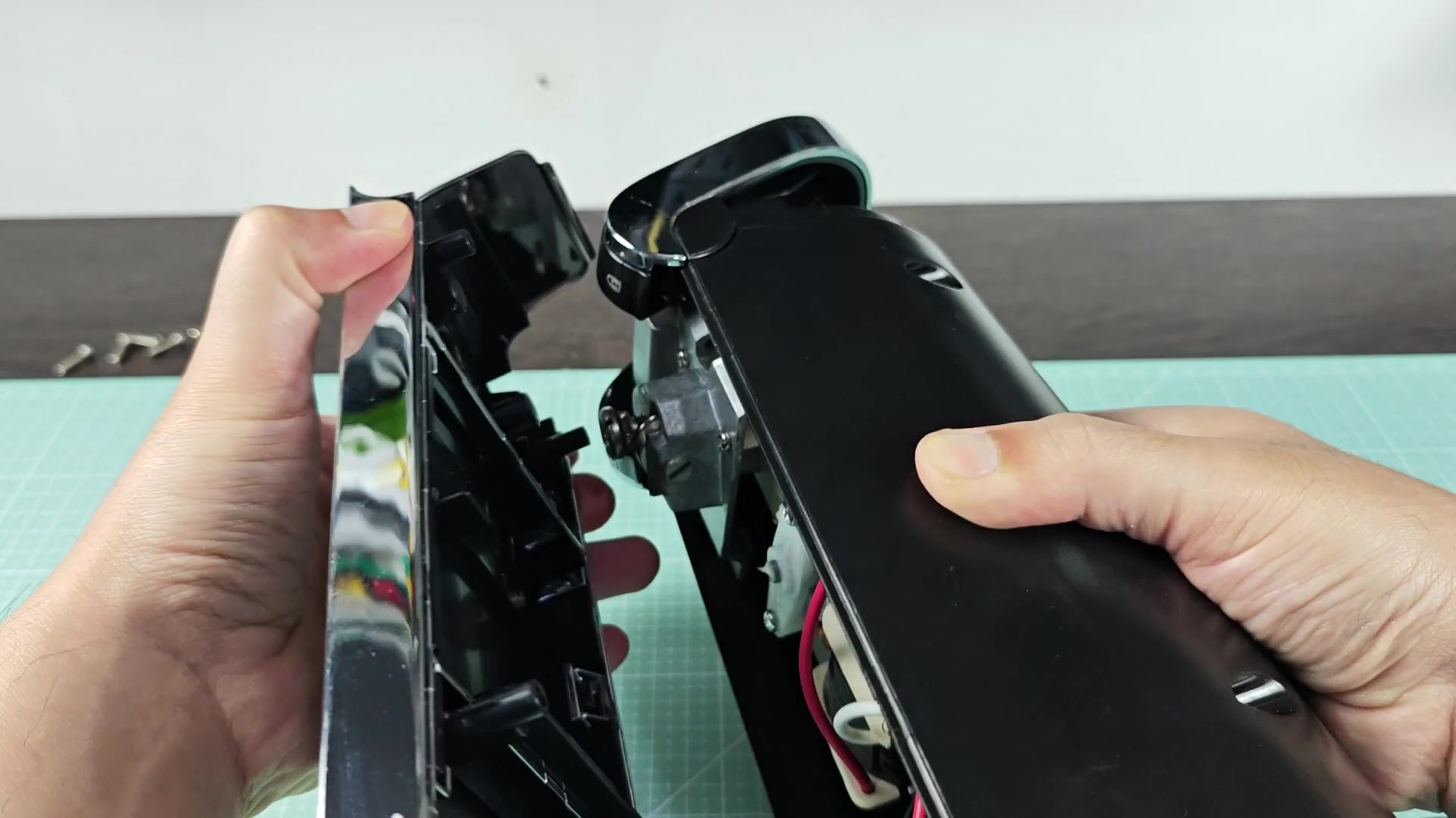
The internal structure reveals a metal gearbox near the cutting wheel.
Lifting the left-side mechanical assembly upward exposes the interior of device which has a metal gearing system just below it. Above that are gears and a locking mechanism. The “LOCKED” label is directly above the gear. That’s the key to keeping the can locked in place while it cuts through your line.
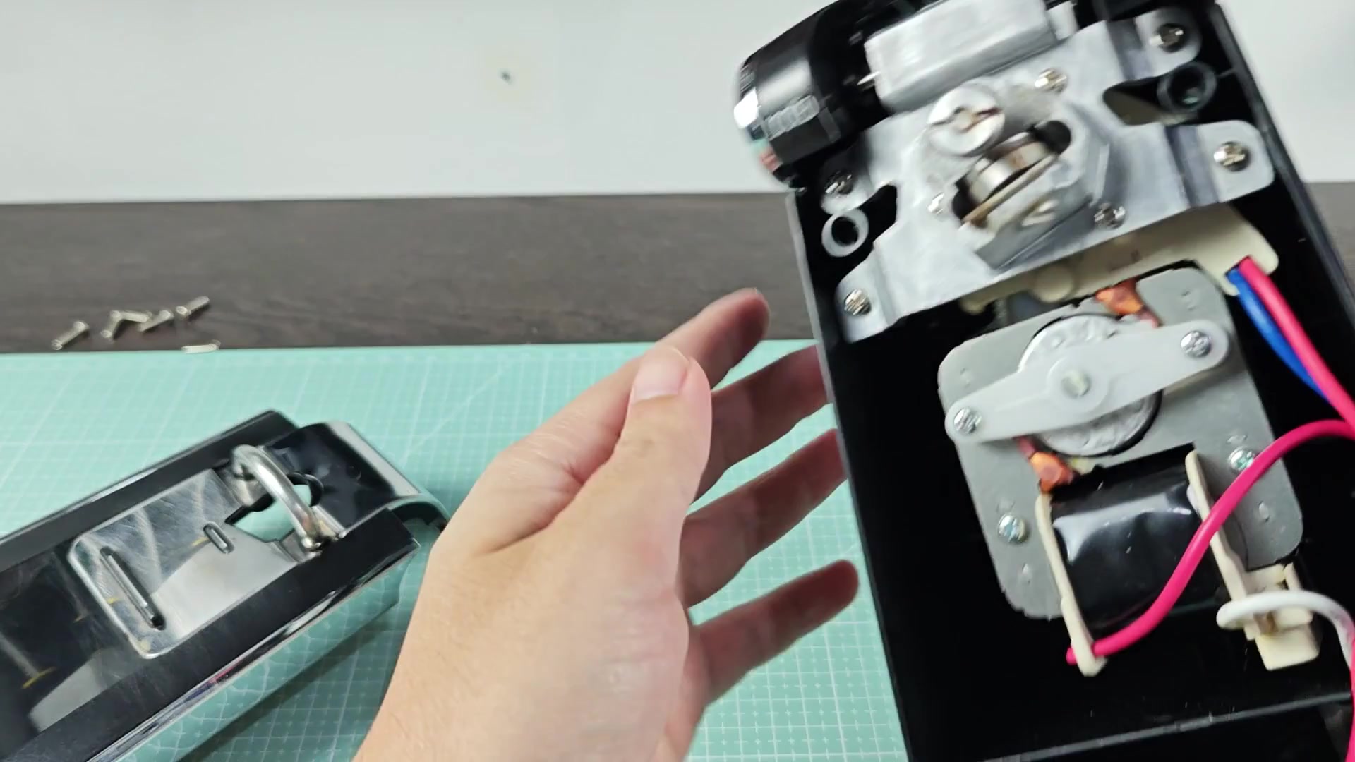
The white plastic gears engage well with the metal gears. It’s not a lot of wiggle room when assembling this thing, everything has to be aligned exactly to work properly. To see more, you raise the entire left-hand mechanical assembly upwards. It reveals the lower section with the gear set contained within the main housing. You can see the large white gear in place in the bottom of the casing. On the right hand side is still the red and blue wires.
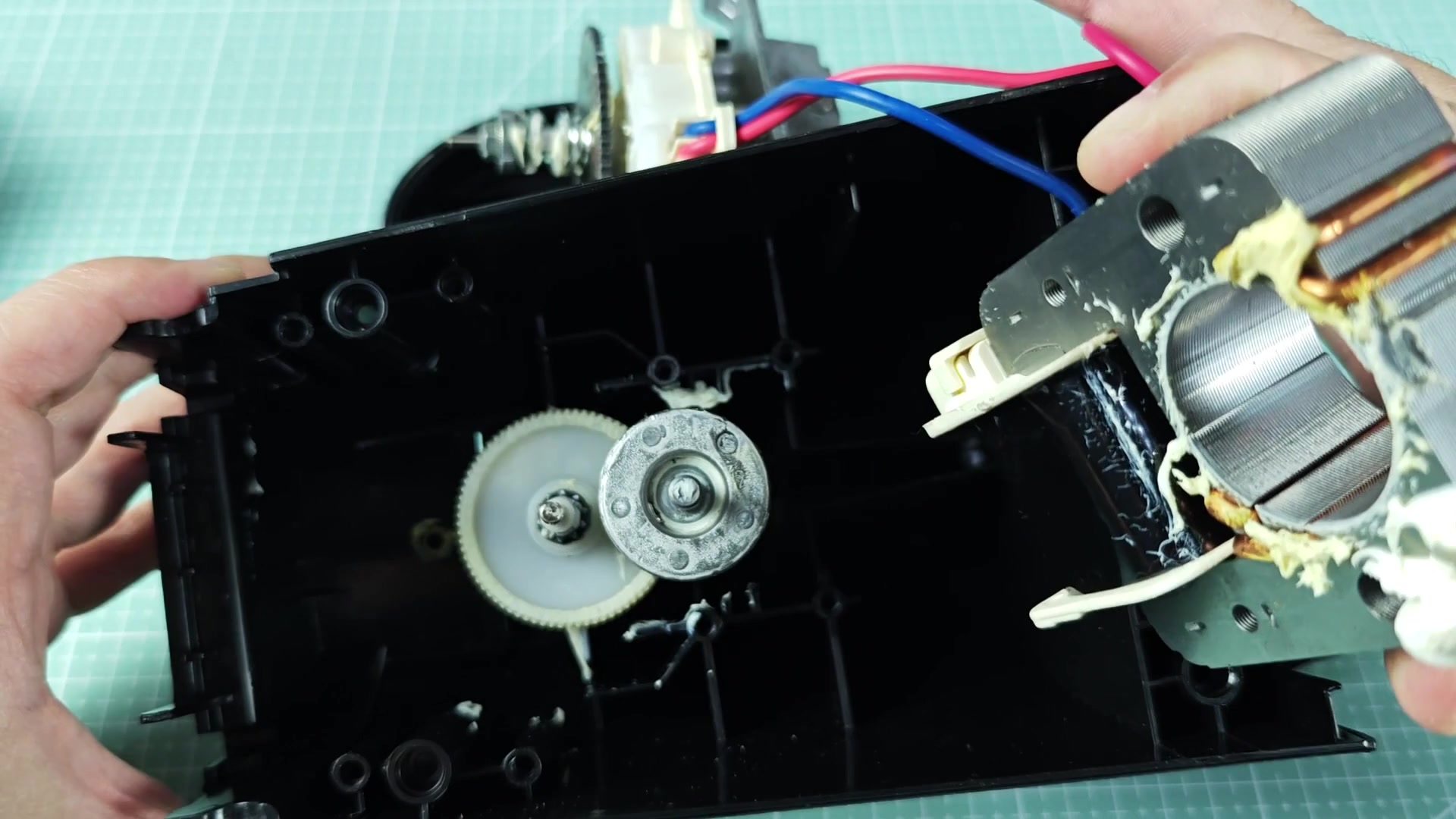
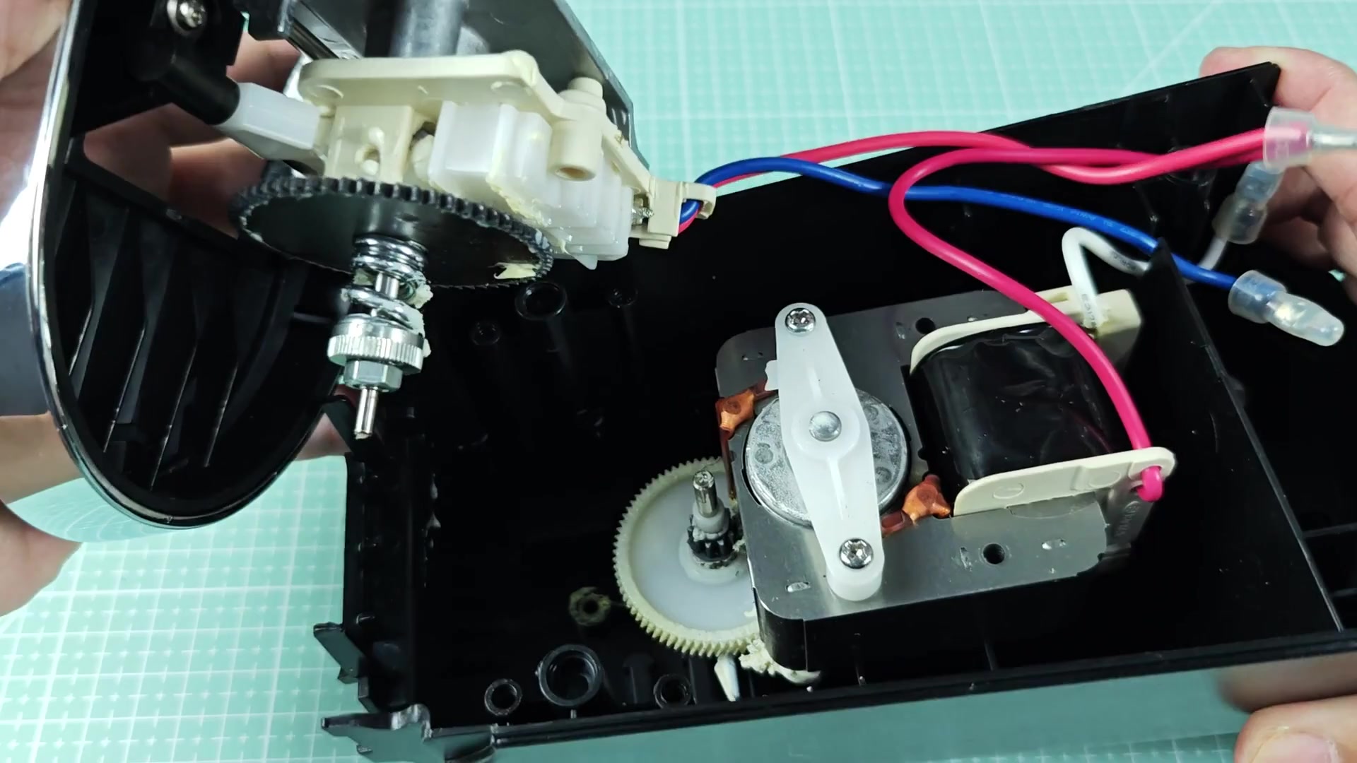
Be careful when lifting the assembly that you don’t yank on the wires too much. They appear well secured at the connection points, so be careful. Now that we have moved the assembly out more you can get a better idea of the drive system. What you notice is the raised section has a large metal gear attached to it. It is this gear which drives the main cutting action. Everything else remains mounted at the bottom base.
So the motor and the coil area are all fixed in place. Now you start to get an idea as to how much power comes from a small motor like this. That’s where the gearing ratio has to be large. Turning the round shroud on its side brings you up next to see how well aligned the shaft is. There are a bunch of washers and nuts followed by a big ol’ metal gear attached right to the white plastic bracket underneath it. And there’s the motor down in the open housing now.
Even though we’ve had this thing apart, all the wires are still in place. It looks nice and clean and not too greasy like you would expect from an appliance used regularily. You notice a white plastic lever arm close to the motor. It looks like an important part of the cutting cycle. To remove, just pry gently on it until it separates from where it mounts.
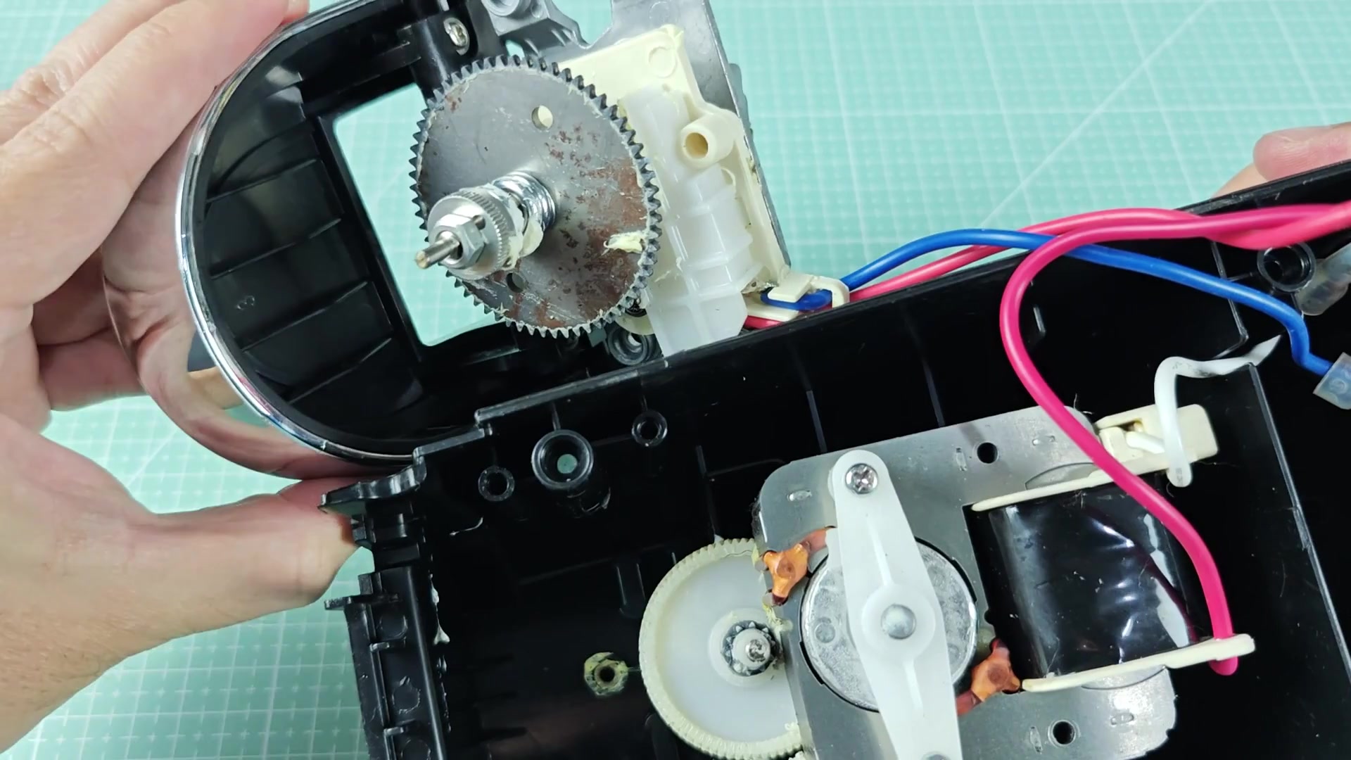
When removed you see a round metal hub in the middle. That hub seems to be the center of the drive mechanism. It is impressive how simple the design is and fewer parts generally mean fewer places for failure. Once we took out the lever arm you could see the motor assembly in the center. The circular metal plate dominates this portion of the device. You will also notice loose hanging red and blue wires.
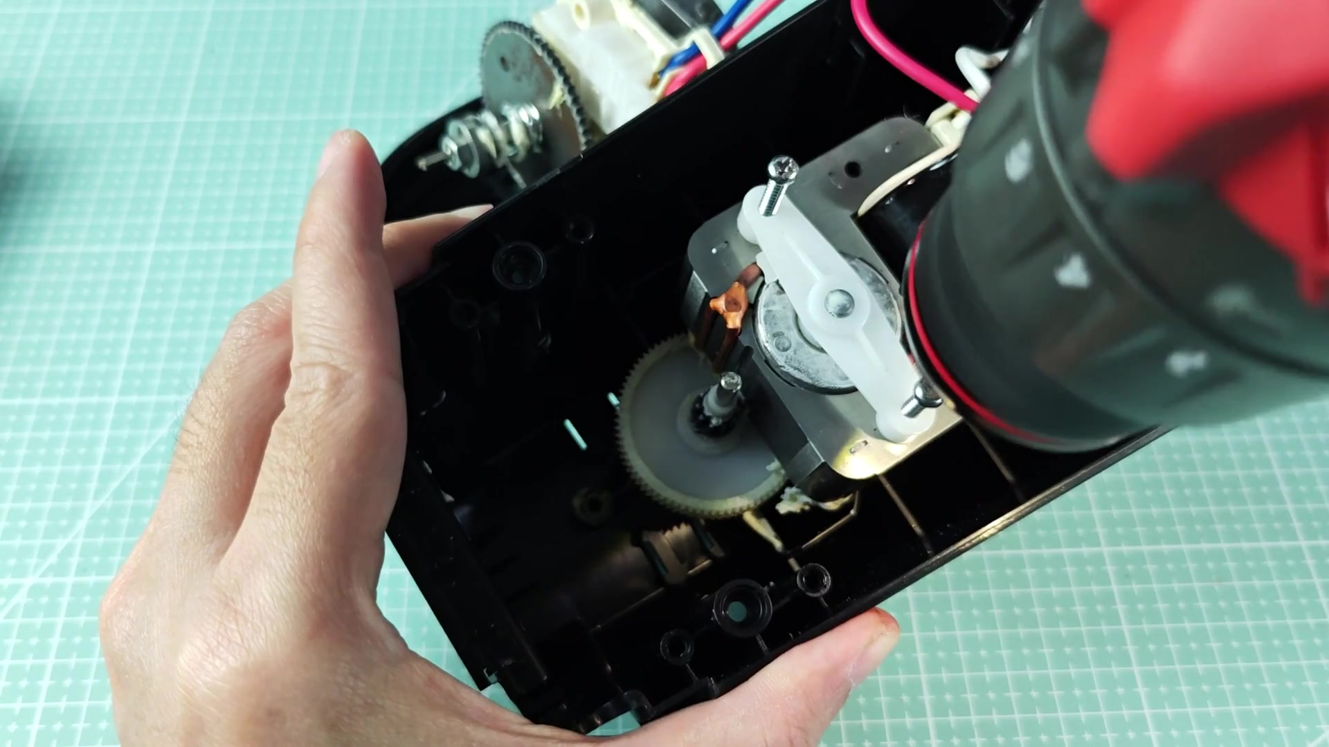
All of these parts are held tight by the housing structure. This allows the force of the motor to be transferred to the gear. The white pieces that connect it all are showing a little bit of wear but no cracks. Overall it’s a pretty good looking device.
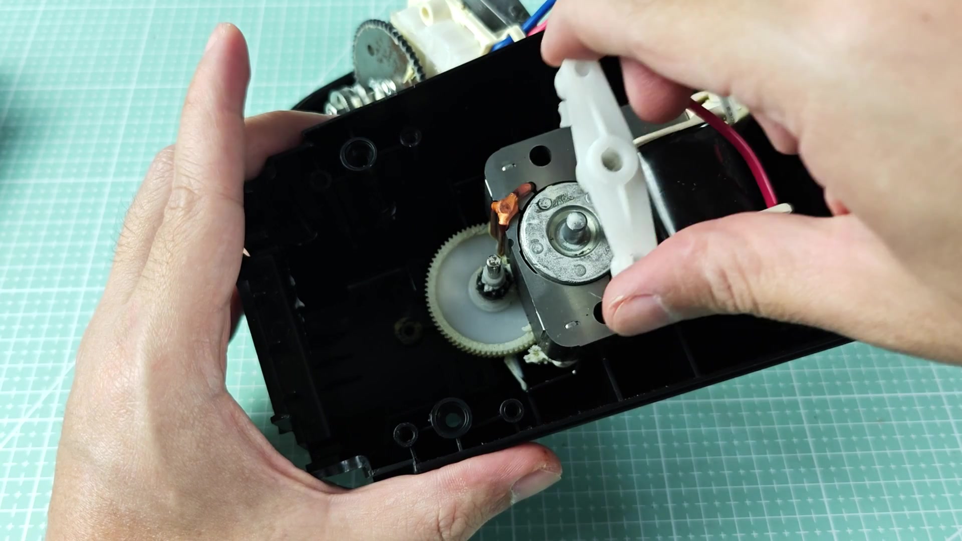
You focus on the shaft where the metal cylindrical component sits.
Look at the shaft that holds the metal cylindrical piece. In this handheld shot you can see how the gears line up perfectly. That’s the metal piece sliding right onto the shaft. It fits snugly against the white gear beneath it, so there isn’t any play or wiggle as it turns. It is precision engineering, even in a budget appliance. It transfers power efficienty. If you notice above I am holding the metal framed cylinder that inserts into the housing. It fits in there perfectly and you can see the red and blue wire coming from it too.
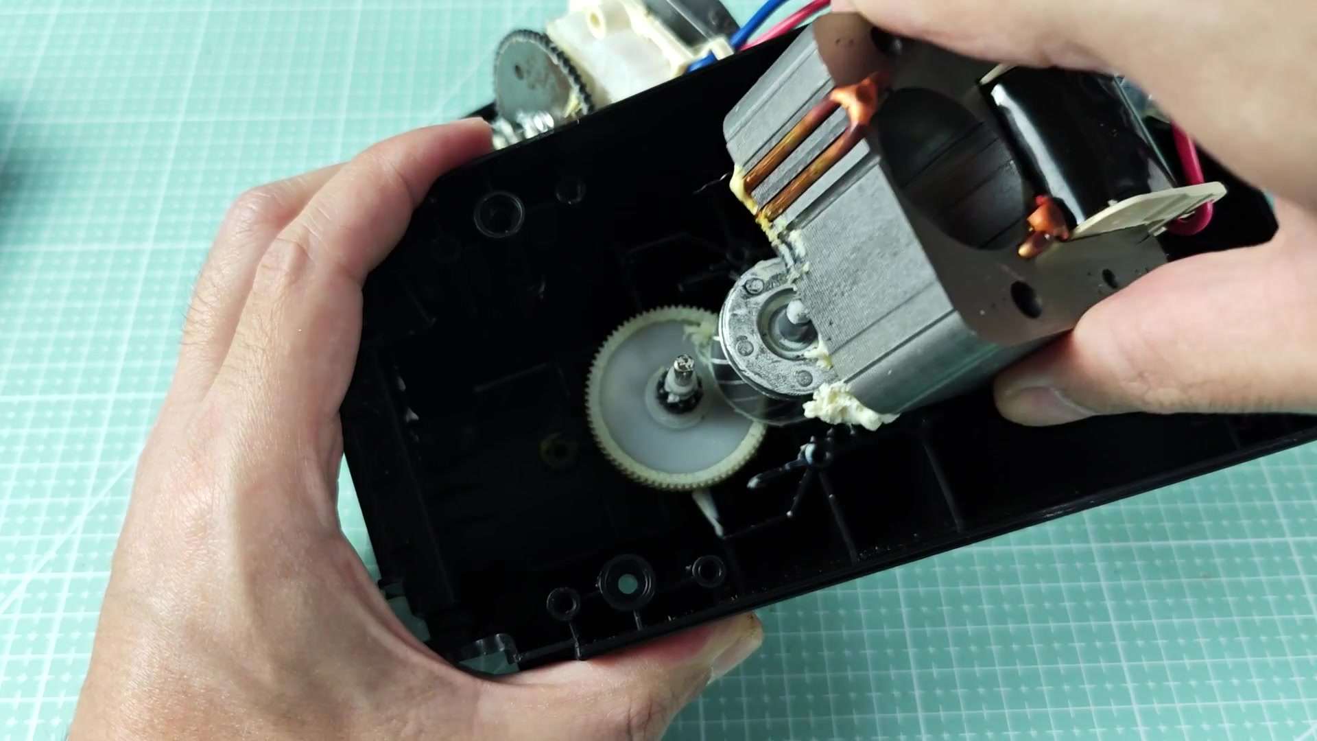
To position it back on the shaft, it has to be aligned exactly right. Once you position it you hold it in place making sure it’s engaged properly. When you put it on right… it’s on right…. No wiggle room at all. Next is the main metal piece that is positioned alongside the white gear which is sitting up on the shaft. This was how it came out of the factory.
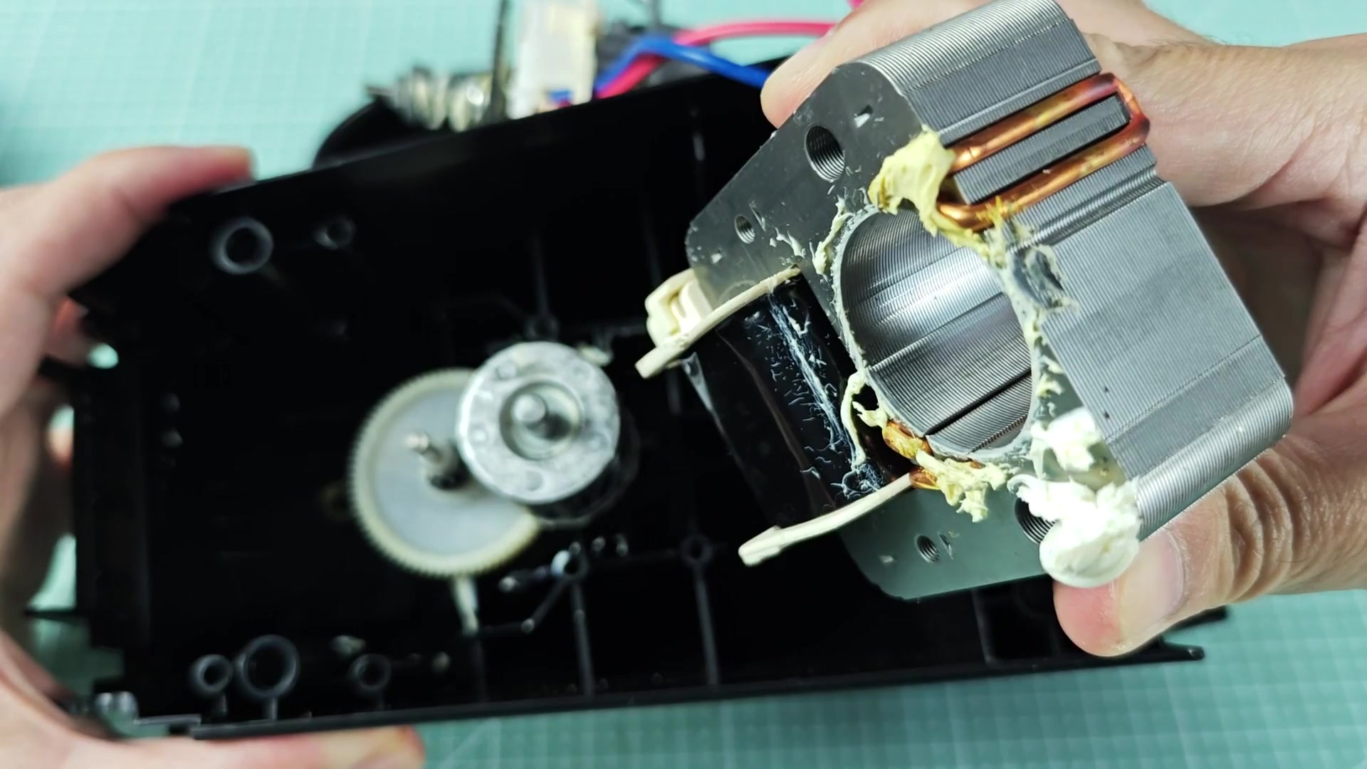
The trick here is not force but alignment. You need to gently slide it in place with your fingers. If you force it you will break something. This process takes time and patience but protects all of the parts from being broken or harmed. And here is a more general picture of what was inside. Now you see the whole thing installed and all the guts laid out. There is the metal part with white gear seated properly. Then the wire section hangs above the opening. It is ready for install but not yet connected.
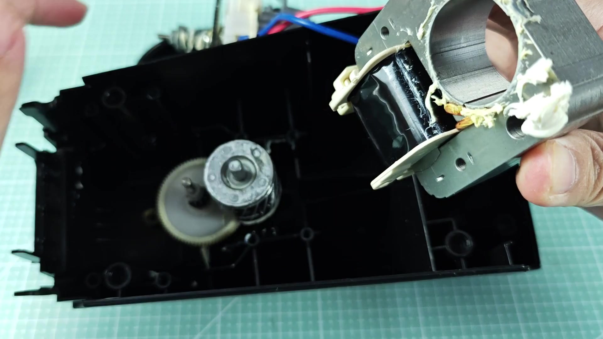
Everything seems like it should make sense and is being done in an orderly manner. It took apart well so we should of expect it to go back together just as easily. You can confidently put this unit back together.